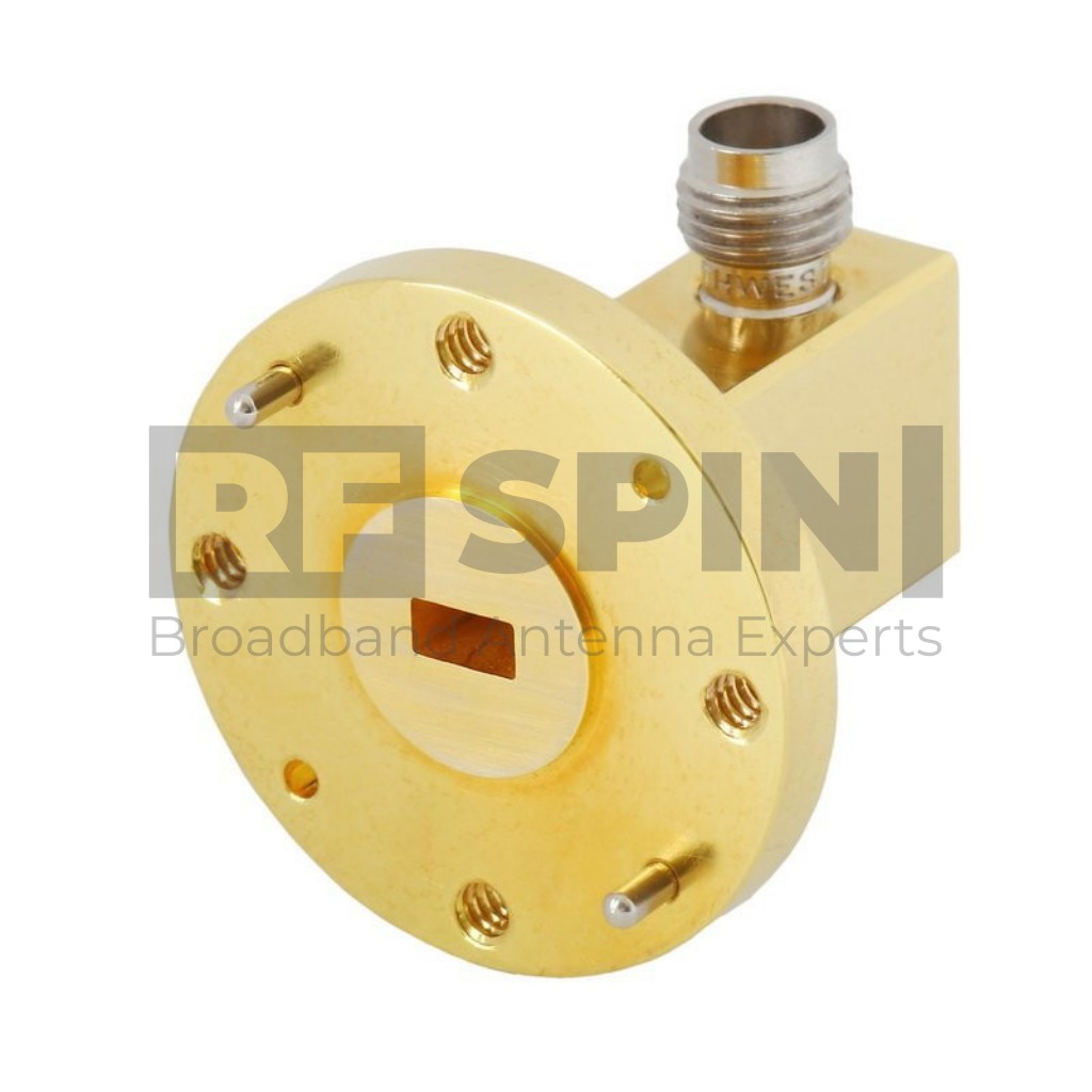
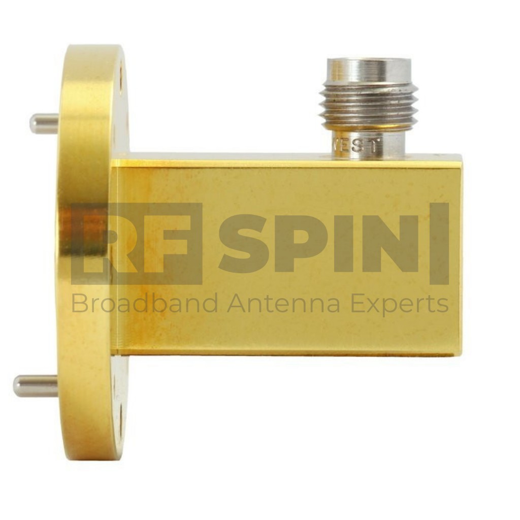
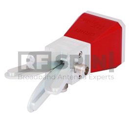
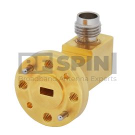
AWC19FV Waveguide to Coax Adapter | 40 GHz – 60 GHz
This Waveguide to Coax Adapter AWC19FV is manufactured with a right-angle design. RF SPIN is using only high-grade aluminum and design with the fewest components to ensure top quality and superb performance. This AWC19FV has waveguide size WR-19 and flange. Using a great quality 1.85mm female connector that is 50 Ohm is a matter of course.
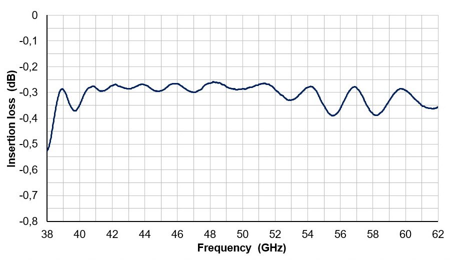
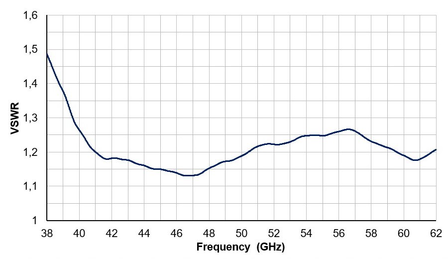
Waveguide to Coax Adapter has a frequency band from 40 GHz up to 60 GHz ensuring the extra performance of VSWR lower than 1.35 and low insertion loss below 0.4 dB.
Frequency Range
40 GHz – 60 GHz
VSWR (avg.)
1.2
Impedance
50 Ohm
Connector
1.85mm (female)
Power (CW / Peak)
5 W / 10 W
In Stock: 5 pcs
Ships in 2 days
Select files to be sent by e-mail
Features and Specifications

Technical Performance
- Low return loss
- Individual calibration

Design and Surface Treatment
- Gold plated coating

Manufacturing Technology
- Manufactured using a high grade aluminum alloy
- Extremely durable
- High quality 1.85mm type coaxial connector

Product Packaging Includes
- Waveguide to Coax Adapter
Product Parameters
Product identification
- Product Name AWC19FV
- Product Category Waveguide to Coax Adapter
Electrical specifications
- Frequency Range 40 GHz – 60 GHz
- VSWR (max.) 1.35
- VSWR (avg.) 1.2
- Impedance 50 Ohm
- Insertion Loss (max.) 0.4 dB
- Connector 1.85mm (female)
- Waveguide Size WR19
- Waveguide Flange UG-383/U-Mod
- Power (CW / Peak) 5 W / 10 W
Physical specifications
- Width 28.7 mm (1.130 in)
- Height 28.7 mm (1.130 in)
- Depth 27.8 mm (1.094 in)
- Weight 0.047 kg (0.104 lb)
Operating conditions
- Rated Temperature Range 0°C – +50°C
- Storage Temperature Range -20°C – +70°C
Parameters and Performance
Typical parameters
Packaging and Accessories
What's in a box
- AWC19FV Device
- Factory calibration certificate
- QR code accessing online portal
- Calibration test dataset (available online)
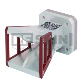
Accessories
- Standard mounting flange
-
 Factory calibration report
Optional Accessories
Manufacturer Information
Other Similar Products


In Stock: 10+ pcs
Ships in 2 days
